I'm fairly certain all your requirements can be met with AutoCAD Electrical. (Wiring diagrams for the people who build the equipment, schematic diagrams for those who have to understand it and make it work). That's the whole point! The same information but for different users. Of course the schematic and wiring diagrams basically show the same thing. Sorry for the long winded question but any help would be greatly appreciated.

How would this affect the BOM and any other reports? So basically I am asking if there is a way to do this in the software where we can show the same point 3 to 4 times on 3 to 4 different drawings in different ways and still have them intelligent / update as one. They are shown on the wiring diagrams, PLC Wiring diagrams and the schematics. This would be true for our cable and wire numbers, I/O points and any other components located in the PLC / Control panels. Any other representations are going to be manual and would not update when changed and we attempt a global update.

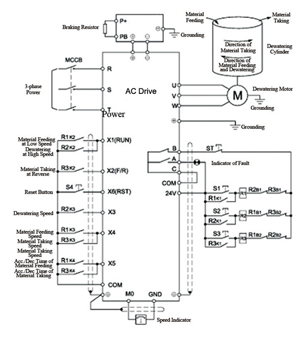
Once on the schematic and once on the layout. So basically my issue is that how they showed us we can only show the same terminal twice. So that in some cases the PLC terminals, breakers and wiring is shown 3 times plus a physical representation is shown on the PLC Panel Layout. Now for most of these drawings we have been told by our reseller that these drawings can be created / manipulated easily but when speaking with them they did not realize that the wiring and schematic drawings basically show the same thing and the PLC panel wiring diagram shows the interfacing terminal strip the cables land on as well. Schematic diagrams (these are the standard idea of a schematic and are more used for concept / PLC programming then actual wiring.) These additional aspects would usually go back to a control panel ie PLC cabinet and possibly through a marshalling panel or junction box) Wiring diagrams (Point to point but showing from the MCC to the VFD to the Motor but also any feedback, coms and control wiring as well. For instance if we were to make a design for a VSD driven motor circuit fed from an MCC bucket we would have to update / create the following drawings: One of our major concerns is as an engineering firm we do not always get to choose how many / what types of drawings we must create. Before we go out for training we are trying to assess if it is worthwile for us.

We have access to the software but are currently creating our documents manually.

We are currently trying to assess if the higher functionality of AcadE is right for us.


 0 kommentar(er)
